Views: 0 Author: Site Editor Publish Time: 2022-07-15 Origin: Site

Roundness measurement includes rotary axis method, three-point method, two-point method, projection method and coordinate method.
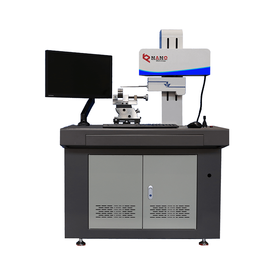
1. Rotary axis method
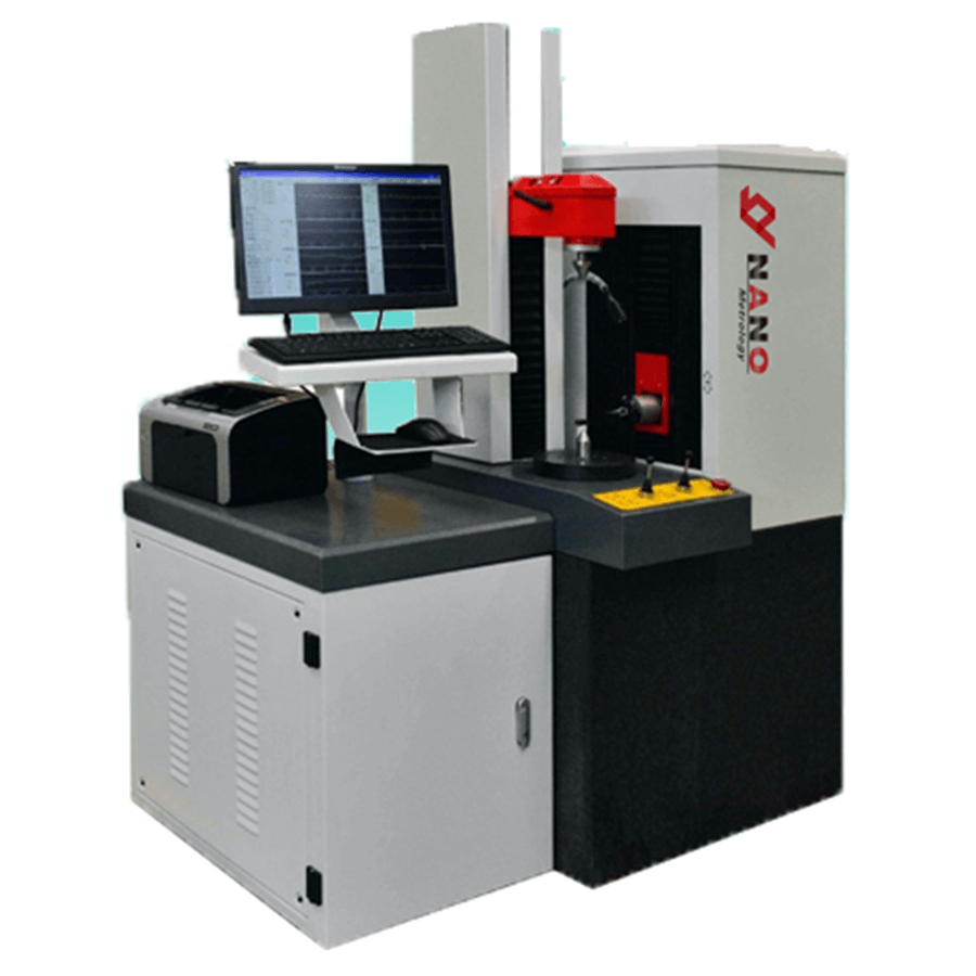
Comparing the circular trajectory (ideal circle) formed by the shaft in the precision shaft system with one revolution with the measured circle, the difference between the two circle radii of the roundness meter is converted into an electrical signal by an electrical length sensor, and processed by a circuit and an electronic computer. After the calculation, the roundness error is indicated by the display instrument, or the measured circle outline graph is recorded by the recorder. The rotary axis method has two forms: sensor rotation and table rotation. The former is suitable for high-precision roundness measurement, while the latter is often used to measure small workpieces. The roundness measuring tool designed according to the rotary axis method is called a roundness meter.
2. Three point method
The workpiece to be measured is often placed in a V-shaped block for measurement. When measuring, make the workpiece to be tested rotate one circle in the V-shaped block, and read the maximum indication value and the minimum indication value from the micrometer. The half of the difference between the two indications is the roundness error of the outer circle of the tested workpiece. This method is suitable for measuring the outer or inner circle with odd-numbered edge shape errors. Two V-shaped blocks with two angles of 90°, 120° or 72° and 108° are commonly used to measure respectively.
3. Two point method
This method is usually measured by a micrometer, a comparator, etc., and the half of the maximum difference between the diameters of a certain section of the measured circle is used as the roundness error of this section. This method is suitable for measuring outer or inner circles with even-numbered edge shape errors.
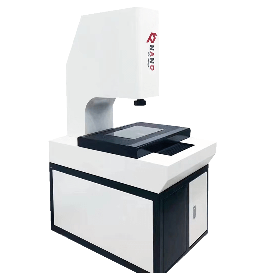
4. Projection method
It is often measured on a projector, and the contour image of the measured circle is compared with the two extreme concentric circles drawn on the projection screen to obtain the roundness error of the measured piece. This method is suitable for measuring small workpieces with edge-shaped edges.
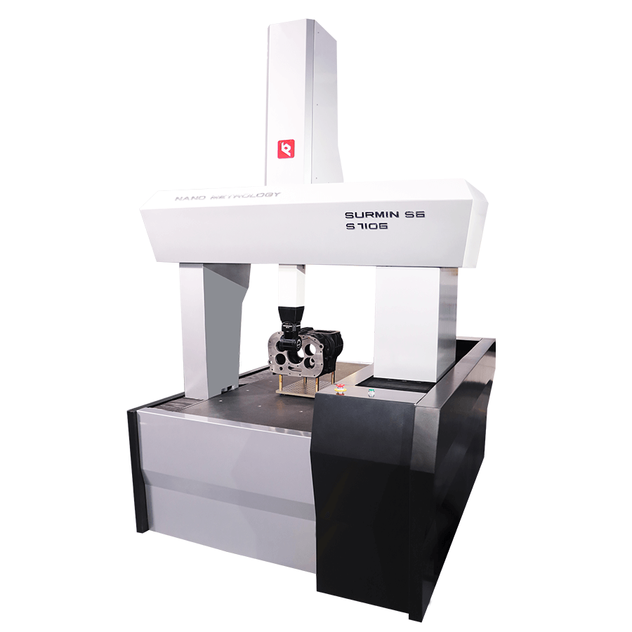
5. Coordinate method
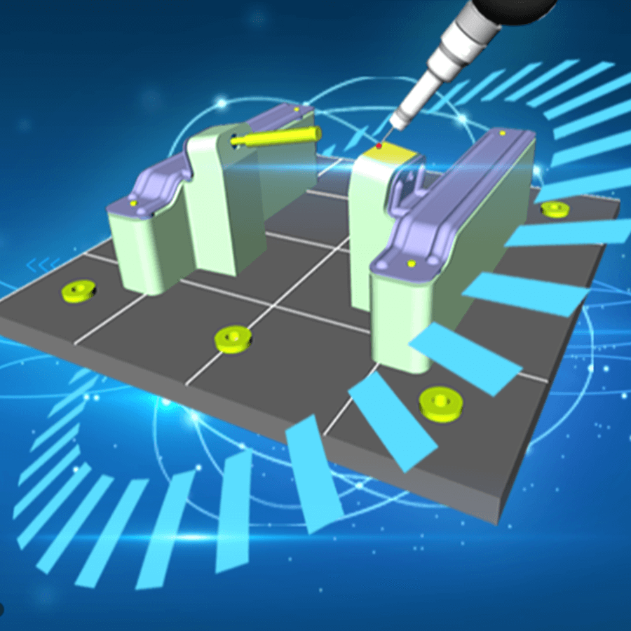
It is generally measured on a three-coordinate measuring machine with an electronic computer. According to the pre-selected rectangular coordinate system, the coordinate values of several points on the measured circle are measured, and the roundness error of the measured circle is calculated by the electronic computer according to the selected roundness error evaluation method.
1. Turn on the gas source, and the gauge pressure reaches 4X10 5 Pa or above.
2. Select the measuring table or accessories according to the size and shape of the workpiece to be measured, and install it on the spindle.
3. Place the workpiece on the measuring table so that it is roughly concentric with the spindle.
4. Press the spindle motor switch, then the spindle starts and drives the worktable to rotate.
5. Press the computer power switch, and after the system is stable, it will enter the adjustment measurement state.
6. In the adjustment state, the computer screen will display the workpiece contour data measured by the sensor in real time according to the circular motion trajectory. -4um).
7. Alignment: First, make a rough adjustment so that the mandrel of the centering device is adjusted to a distance of about 1.0mm~1.2mm from the workpiece and lock it tightly, and the probe of the sensor is adjusted to a distance of about 1mm~1.2mm from the workpiece. After the distance is locked, then use the fine-tuning to make the sensor touch the workpiece, adjust the workpiece with the fine-tuning knob of the centering device, until the sensor all touches the workpiece, that is, the outline of the workpiece is completely displayed on the computer screen, and then the top rod of the centering device is adjusted. Retract it from the workpiece, and move the fine-tuning sensor forward 2~3 small grids (equivalent to adding a measuring force of 0.6~1N). This completes the adjustment process.
8. After that, press the measurement button to start the measurement according to the prompt on the screen. The workpiece rotates once and the measurement is completed. At this time, the screen graphics and analysis values are displayed in real time.
9. When measuring small workpieces, the spindle can be stopped, the sensor can be withdrawn, and the workpiece can be removed. If the workpiece to be tested is very large, the spindle must be stopped before the workpiece to be tested can be replaced.
10. When measuring the roundness of the raceway of the ring, it is generally only necessary to visually observe that the probe is in the middle of the raceway. If the process test is to be done, it is required that the section of each measurement remains unchanged, and the bottom of the groove (the center of the raceway) must be carefully found.
1. Always use a multimeter to check the air flotation of the spindle, especially when the measured value changes greatly, first check whether the spindle works normally. If it is found that there is a slight contact or no floating, etc., the measurement should be stopped immediately, and the spindle should be removed for cleaning or returned to the manufacturer in the original packing box for inspection and maintenance.
2. The filter should be regularly drained of water, oil, etc. The filter material installed in the filter must be dried or replaced regularly according to the local climate and the water and oil conditions of the compressed air, and the filter should be cleaned at the same time. Remove the filter and check it about once a year.
3. The sensor probe must be cleaned frequently to wipe off the oil on the probe. When the probe is severely worn, the probe can be replaced.
4. If the sensor crystal is found to be broken, it must be returned to the manufacturer for repair, and can be used after re-calibration.
5. The computer should be kept clean, dust-proof and moisture-proof.