|


The software rightly configures the machine movement parameters and environmental ones.
The measuring software package has an English version. Except operation interface, the part program and output reports are in English, moreover, the language is available to be switched to another certain language. You can get online help if necessary. The operation brochure and the training material are provided to users.
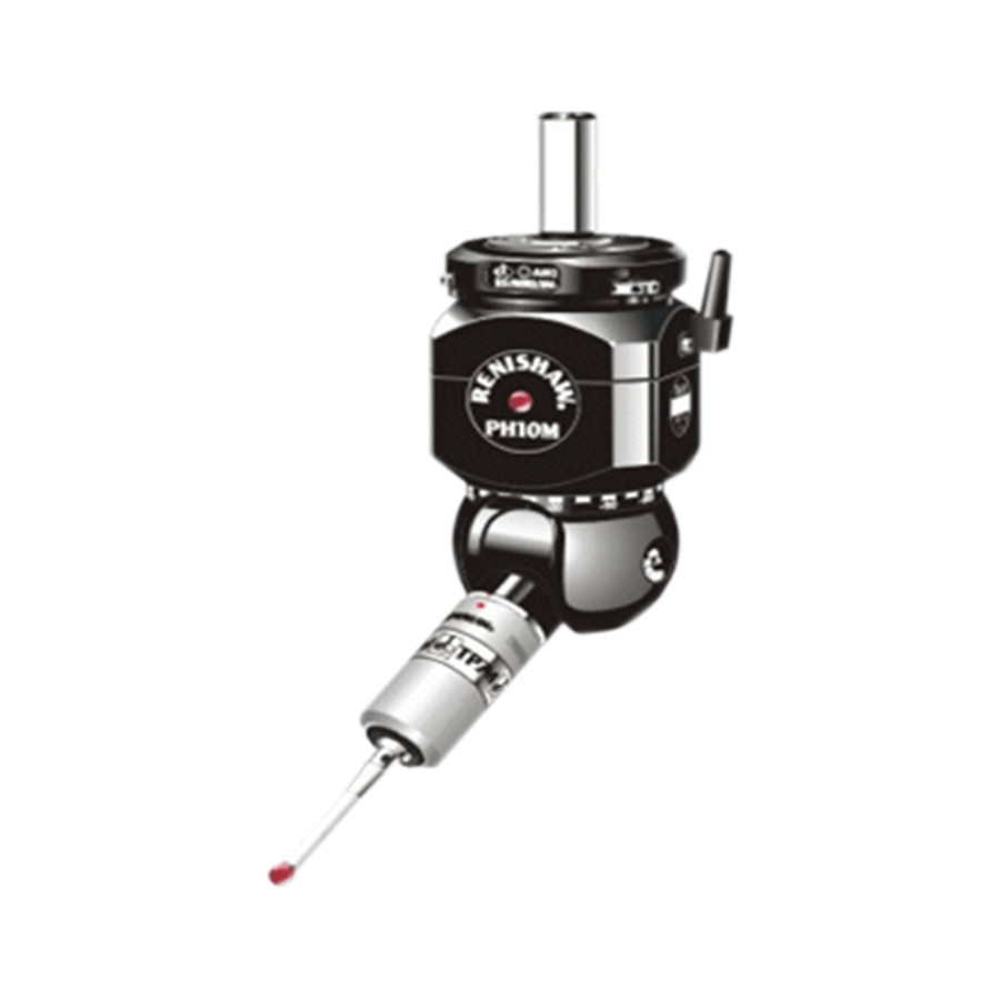
The software has the function of probe system configuration and adjustment. The probe’s control and its diameter’s preference is set by the software. The stylus is adjusted automatically, the result’s judgment method is also supplied by the software, which is quite simple and speedy. An automatic adjustment program is then created to adjust a certain probe alone.
The software can build a measuring-coordinate system with a certain basic measured element group.
Except the basic 3-2-1 part-position finding function, the measuring software package also can be used to find the exact position of a part especially with free-form surfaces, in the iterative method or the best match way.
The user can build a measuring-coordinate system with the basic elementary group and part of its vectors by the best fit method.
The name and the direction of the measuring-coordinate system can be adjusted according to users’ needs.
The measuring-coordinate system can be translated and rotated according to users’ needs.
A measuring-coordinate system can be built with structural elements.
The user can get measuring points by the software.
Such basic geometric elements’ measurement as points(planar points and spatial points), lines, planes, circles, ellipses, rectangles, circular cones, cylinders, circular rings and balls. It can be finished automatically for right parts under the measuring program.
Some motions can be finished by the software, such as the element’s structuring, switching, representation, projection, storage, calling and some other related computing.
The user can build the coordinate system or the work-piece coordinate system with the software. The two kind of coordinate systems also can be stored, called or switched.
Dimensional tolerance evaluation, geometric tolerance evaluation.
The file of measurement results may be stored or input through the software.
Under the graphics drive, fast programming is realized. So that the object is finally measured.
The software has the function of digital-analog theoretical element automatic recognition. then the measuring program is fast created.
The point is probed as soon as the stylus touches it. In this way, the measurement efficiency is improved.
The software can computing and switch a certain geometric element group into some another geometric element. For example, it can make a circle out of many points, or make a surface.
The software can calculate the relation between or among geometric elements, such as distance, intersection, projection, and angularity, etc.
The software can calculate such geometric errors as linearity, flatness, roundness, cylindricity, parallelism, verticality, symmetry, concentricity, coaxiality, section run-out, radial run-out and total run-out, etc.
The software can differently color and mark the error which surpassed the set value.
The excellent human machine interface is easy to operate. And the operation software interface is displayed in English.
The software can self-calculate and generate a program automatically. Then the software also can simulate to run measuring program.
The pure DMIS kernel is 100 percent up to the DMIS standard.
Some usual DMIS sentences, functions and macros are embedded.
The software can self-calculate to create standard DMIS sentences.
Manual mode: the user can operate the control stick to measure something.
The self-calculation and memory mode: after the mode, the manual measurement process can be remembered and finally becomes part of the program.
Repeat mode: this mode can call part of the program to measure something.
Editing mode: this program can add points to measure and can modifier part of the program.
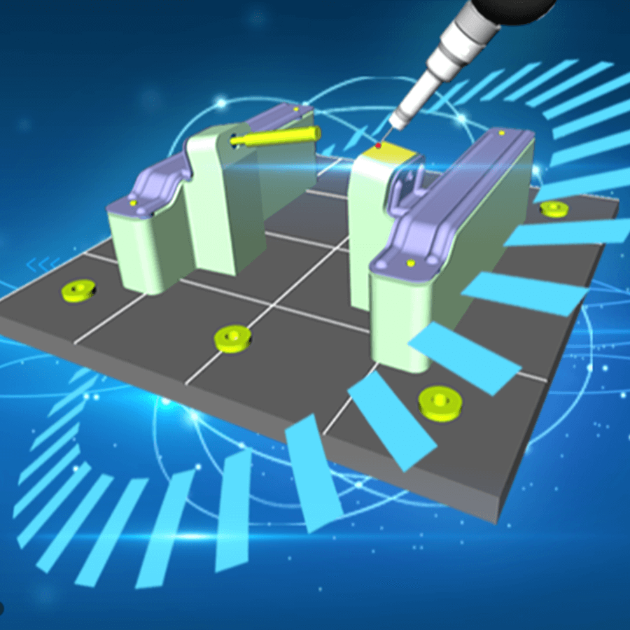
100 percent graphic demonstration. The measuring software package should has the graphic demonstration function, namely, all the measurement and calculation elements can be graphically displayed and operated.
The machine model is graphically built, so are these operation such as probe building, calibration, measurement, structure, tolerances and outputting. Such functions as graphically displaying, path simulation, collision test and measurement plan can improve measurement’s operability and predictability. This will make the operation safer and reduce the hardware getting broken risk, maybe due to wrong operation or unskilled operation.
Various graphical output reports.
Offline measuring simulation, interference detection.
The measuring software package is applied to reverse engineering, and outputs something in IGES format. It makes 3-D graph out of some certain basic elements, then uploads this graph to computer-aided design system software, such as UG, PROE. In this case, the unknown part is measured and drawn, then the mathematical model is uploaded to the design software to be processed.
The data can be stored, then switched and edited in EXCEL software. It is printed directly or printed according to the user-required form.
The data, gotten through 3-D coordinate measurement, may be switched into the report mode. Then the user also can edit the report.
Data output: LCD, printer.
The software rightly configures the machine movement parameters and environmental ones.
The measuring software package has an English version. Except operation interface, the part program and output reports are in English, moreover, the language is available to be switched to another certain language. You can get online help if necessary. The operation brochure and the training material are provided to users.
The software has the function of probe system configuration and adjustment. The probe’s control and its diameter’s preference is set by the software. The stylus is adjusted automatically, the result’s judgment method is also supplied by the software, which is quite simple and speedy. An automatic adjustment program is then created to adjust a certain probe alone.
The software can build a measuring-coordinate system with a certain basic measured element group.
Except the basic 3-2-1 part-position finding function, the measuring software package also can be used to find the exact position of a part especially with free-form surfaces, in the iterative method or the best match way.
The user can build a measuring-coordinate system with the basic elementary group and part of its vectors by the best fit method.
The name and the direction of the measuring-coordinate system can be adjusted according to users’ needs.
The measuring-coordinate system can be translated and rotated according to users’ needs.
A measuring-coordinate system can be built with structural elements.
The user can get measuring points by the software.
Such basic geometric elements’ measurement as points(planar points and spatial points), lines, planes, circles, ellipses, rectangles, circular cones, cylinders, circular rings and balls. It can be finished automatically for right parts under the measuring program.
Some motions can be finished by the software, such as the element’s structuring, switching, representation, projection, storage, calling and some other related computing.
The user can build the coordinate system or the work-piece coordinate system with the software. The two kind of coordinate systems also can be stored, called or switched.
Dimensional tolerance evaluation, geometric tolerance evaluation.
The file of measurement results may be stored or input through the software.
Under the graphics drive, fast programming is realized. So that the object is finally measured.
The software has the function of digital-analog theoretical element automatic recognition. then the measuring program is fast created.
The point is probed as soon as the stylus touches it. In this way, the measurement efficiency is improved.
The software can computing and switch a certain geometric element group into some another geometric element. For example, it can make a circle out of many points, or make a surface.
The software can calculate the relation between or among geometric elements, such as distance, intersection, projection, and angularity, etc.
The software can calculate such geometric errors as linearity, flatness, roundness, cylindricity, parallelism, verticality, symmetry, concentricity, coaxiality, section run-out, radial run-out and total run-out, etc.
The software can differently color and mark the error which surpassed the set value.
The excellent human machine interface is easy to operate. And the operation software interface is displayed in English.
The software can self-calculate and generate a program automatically. Then the software also can simulate to run measuring program.
The pure DMIS kernel is 100 percent up to the DMIS standard.
Some usual DMIS sentences, functions and macros are embedded.
The software can self-calculate to create standard DMIS sentences.
Manual mode: the user can operate the control stick to measure something.
The self-calculation and memory mode: after the mode, the manual measurement process can be remembered and finally becomes part of the program.
Repeat mode: this mode can call part of the program to measure something.
Editing mode: this program can add points to measure and can modifier part of the program.
100 percent graphic demonstration. The measuring software package should has the graphic demonstration function, namely, all the measurement and calculation elements can be graphically displayed and operated.
The machine model is graphically built, so are these operation such as probe building, calibration, measurement, structure, tolerances and outputting. Such functions as graphically displaying, path simulation, collision test and measurement plan can improve measurement’s operability and predictability. This will make the operation safer and reduce the hardware getting broken risk, maybe due to wrong operation or unskilled operation.
Various graphical output reports.
Offline measuring simulation, interference detection.
The measuring software package is applied to reverse engineering, and outputs something in IGES format. It makes 3-D graph out of some certain basic elements, then uploads this graph to computer-aided design system software, such as UG, PROE. In this case, the unknown part is measured and drawn, then the mathematical model is uploaded to the design software to be processed.
The data can be stored, then switched and edited in EXCEL software. It is printed directly or printed according to the user-required form.
The data, gotten through 3-D coordinate measurement, may be switched into the report mode. Then the user also can edit the report.
Data output: LCD, printer.