Views: 0 Author: Site Editor Publish Time: 2022-10-27 Origin: Site

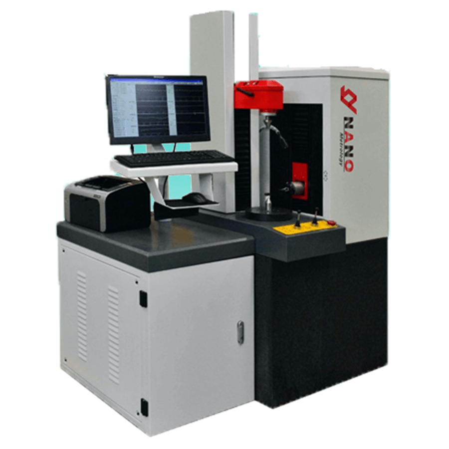
According to the requirements of out of roundness measurement, the roundness tester must have three characteristics: (1) It has a high-precision spindle to realize the centering of parts and determine the center of the theoretical circle at the same time. (2) A sensor with high sensitivity. When it revolves around the center of the spindle, it can measure the small out of roundness error of the part. (3) A device with continuous indication or recording. In order to record the actual contour of the part for analysis and evaluation.
Roundness measurement methods include rotary axis method, three-point method, two-point method, projection method and coordinate method.
1. Rotary axis method.
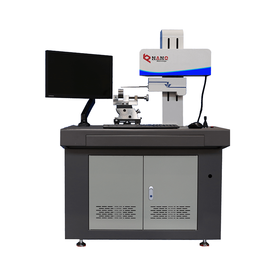
Compare the circle track (ideal circle) formed by one revolution of the shaft in the precision shafting with the measured circle. The difference between the radii of the two circles is converted into an electrical signal by an electrical length sensor. After circuit processing and computer calculation, the roundness error is indicated by a display instrument, or the contour figure of the measured circle is recorded by a recorder. The rotation axis method has two forms: sensor rotation and workbench rotation. The former is suitable for high-precision roundness measurement, while the latter is commonly used for measuring small workpieces. The roundness measuring tool designed by the rotary axis method is called the roundness meter.
2. Three-point method
The measured workpiece is often placed in a V-shaped block for measurement. During measurement, rotate the measured workpiece in a V-shaped block for one circle, read the maximum and minimum indication from the micrometer, and half of the difference between the two indications is the roundness error of the outer circle of the measured workpiece. This method is applicable to measuring the outer circle or inner circle with odd edge shape error. Usually, two V-shaped blocks with 90 °, 120 ° or 72 °, 108 ° angles are measured separately.
3. Two point method
Micrometer and comparator are commonly used for measurement, and half of the maximum difference between diameters on a section of the measured circle is taken as the roundness error of the section. This method is suitable for measuring outer circle or inner circle with even edge shape error.
4. Projection method
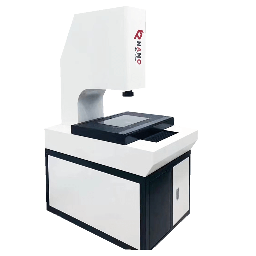
It is often measured on the projector. Compare the contour image of the measured circle with the two limit concentric circles drawn on the projection screen to obtain the roundness error of the measured piece. This method is suitable for measuring small workpieces with edge shape.
5. Coordinate method
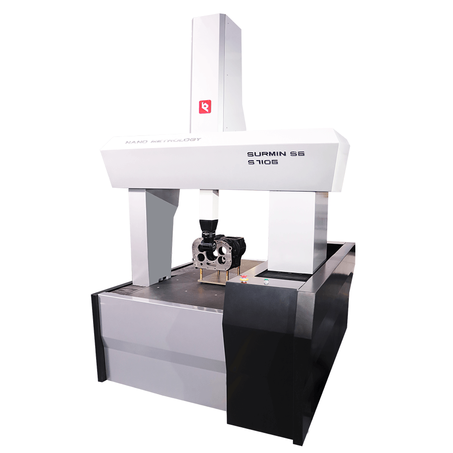
It is generally measured on a CMM with an electronic computer. Measure the coordinate values of several points on the measured circle according to the pre selected rectangular coordinate system, and calculate the roundness error of the measured circle according to the selected roundness error evaluation method through an electronic computer.
The main factors affecting the measuring accuracy of the roundness tester are:
1. Spindle rotation accuracy. The roundness meter measurement is actually a comparative measurement process, that is, the circumference drawn by the measuring head relative to the workpiece rotation is compared with the measured contour. Therefore, the rotation accuracy of the spindle directly affects the uncertainty of the measurement results.
2. Workpiece installation error. It includes two situations: the center deviation of the measured workpiece relative to the roundness tester and the inclination of the center line of the measured workpiece relative to the spindle of the instrument.
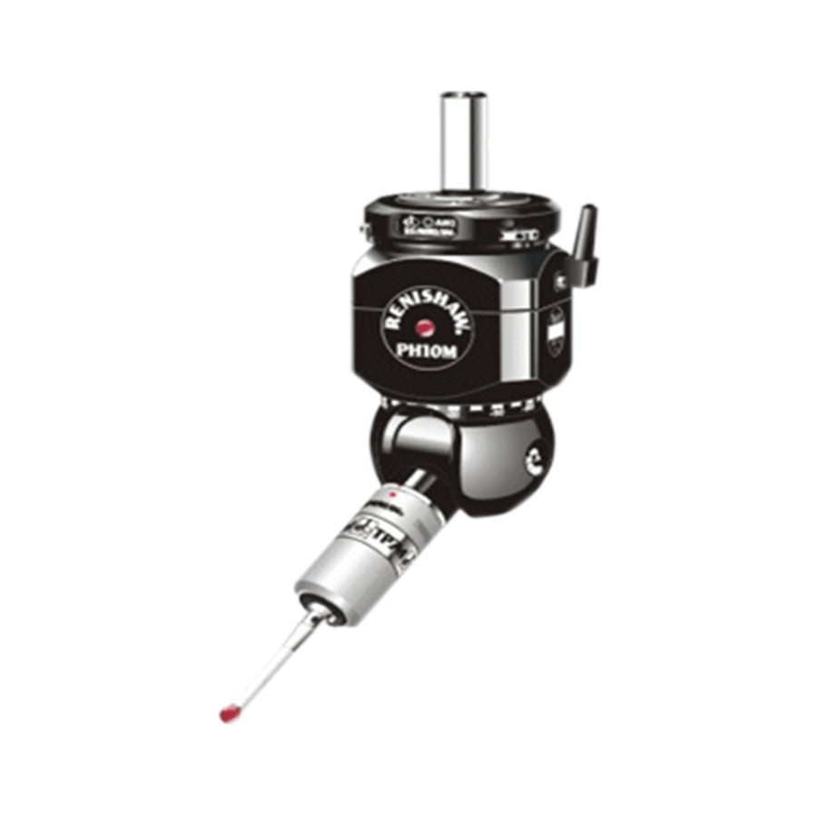
3. Selection of probe shape and radius. It is important to choose the shape and radius of the contact correctly for measuring the roundness error. The selection of shape and radius is mainly based on the characteristics of the workpiece surface, taking into account the hardness of the workpiece and other factors. In order to avoid the influence of micro geometric shapes such as surface roughness, the needle shaped probe should not be used, but the spherical or axe shaped probe should be used. Cylindrical probe can be used for smaller workpieces. For workpieces with low hardness, use a probe with a larger radius to prevent plastic deformation of the workpiece surface.
4. Measure the effect of the force. The choice of measuring force is that the measured surface will not produce plastic deformation, and the probe will keep stable contact with the measured surface.
1. Appearance
The working surface of the instrument shall be free of rust and bruise, and the coated surface shall be flat and even without spots, peeling, etc. The junction of external parts shall be neat.
For parts with engraved lines and words, the words and lines shall be clear and uniform. There shall be no oil leakage.
2. Interaction and mutual position
The movable parts of the instrument shall move smoothly within the specified range.
The action of various buttons, operating parts and limit devices shall be flexible, reliable and functional.
The instrument measurement direction shall pass through the spindle rotation center.
The record scope shall be consistent with the knowledge scope of the alignment table.
3. Amplifier conversion error
The calibration error shall not be greater than 1%.
This series of instruments are widely used in mechanical processing, motor, auto parts, motorcycle parts, precision hardware, precision tools, knives, molds, optical components and other industries. It is applicable to scientific research institutes, colleges and universities, measurement institutions, enterprise measurement rooms and workshops. It can measure bearings, steel balls, needles, rollers, motor shafts, commutators, crankshafts, cylindrical pins, piston pins, pistons, valves, gears, oil pump nozzles, hydraulic parts, pneumatic parts, textile machine accessories, etc.