Views: 0 Author: Site Editor Publish Time: 2023-04-07 Origin: Site

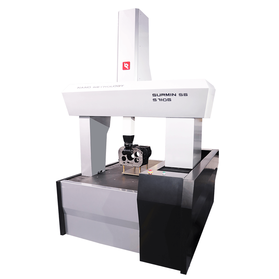
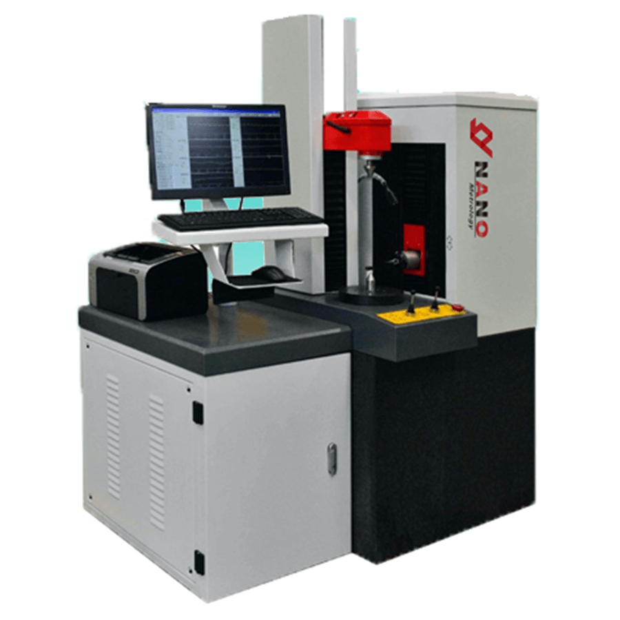
In modern machines, the gantry-type superstructure has two legs, often called bridges.It moves freely along the granite countertop with one leg (often called the inside leg) along a rail attached to one side of the granite countertop.The other leg (usually the outside leg) simply rests on the granite countertop following the vertical surface contour.Air bearings are the method of choice to ensure frictionless travel.In it, compressed air is forced through a series of very small holes in a flat bearing surface to provide a smooth but controllable air cushion on which the CMM can move in a frictionless manner.The movement of the bridge or gantry along the granite table forms an axis in the XY plane.The bridge of a gantry consists of a carriage that traverses between the inner and outer legs and forms another X or Y horizontal axis. A third axis of motion (Z-axis) is provided by the addition of a vertical sleeve or spindle which can move up and down through the center of the carriage.The contact probe forms the sensing device at the end of the sleeve.
The movement of the X, Y and Z axes completely describes the measuring range.An optional turntable is available to enhance the accessibility of the measuring probe to complex workpieces.A rotary table as a fourth drive axis doesn't add to the still 3D
measurements, but it does offer a degree of flexibility. Some touch probes are themselves powered swivel units, with the probe tip capable of vertical 90° rotation and a full 360° rotation.In addition to traditional three-axis machines (pictured above), CMMs are now available in a variety of other formats.These include the CMM Arm, which uses angular measurements made at the arm's joints to calculate the position of the stylus tip.This arm-mounted CMM is often used where its portability is superior to traditional fixed-bed CMMs.Because CMM arms mimic the dexterity of a human arm, they are also often able to reach the interior of complex parts that cannot be probed using standard three-axis machines.

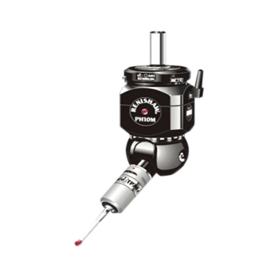
In early CMM coordinate measuring machines, a mechanical probe was mounted in a special bracket at the end of the spindle.A very common probe is made by welding a hard ball to the end of the shaft.This is ideal for measuring a variety of flat, cylindrical or spherical surfaces.Other probes are ground into specific shapes, such as quadrants, to enable measurements of special functions. These probes are physically affixed to the workpiece and the spatial position is read from a 3-axis digital readout (DRO) or, in more advanced systems, logged to a computer via a foot switch or similar device.Measurements by this contact method are often unreliable because the machine is moved by hand and each machine operator applies different pressures on the probe or employs different measurement techniques.A further development was the addition of motors to drive each axis.Instead of physically touching the machine, the operator can use a joystick to drive each axis, just like a modern remote-controlled car.With the invention of electronic trigger probes, measurement accuracy and precision have improved dramatically.The pioneer of this new probe device was David McMurtry, who later founded what is now Renishaw plc.
Although still a contact device, the probe had a spring-loaded steel ball (later ruby ball) stylus. As the probe touched the surface of the component the stylus deflected and simultaneously sent the X.Y,Z coordinate information to the computer. Measurement errors caused by individual operators became fewer and the stage was set for the introduction of CNC operations or Direct Computer Controlled and the coming of age of DCC CMMs.
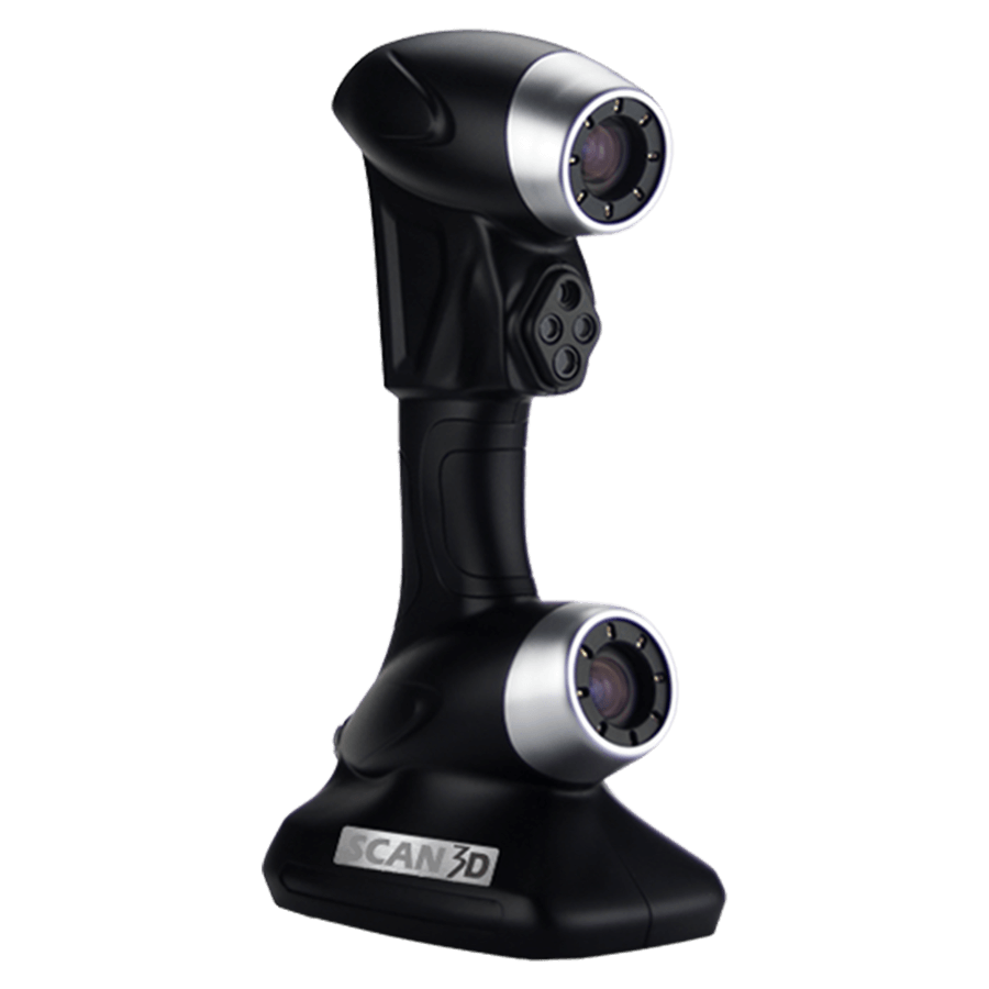
Non-Contact probes
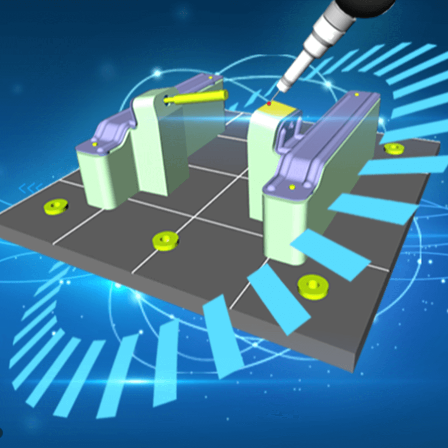
Optical probes are lens-CCD-systems, which are moved like the mechanical ones, and are aimed at the point of interest, instead of touching the material.The captured image of the surface will be enclosed in the borders of a measuring window, until the residue is adequate to contrast between black and white zones.The dividing curve can be calculated to a point, which is the wanted measuring point in space.The horizontal information on the CCD is 2D (XY) and the vertical position is the position of the complete probing system on the stand Z-drive (or other device component).This allows full 3D probing. New detection system.There are newer models that have a probe that is dragged along the surface of the part, taking points at specified intervals, called CORE.This method of CMM inspection is generally more accurate and most of the time faster than traditional touch probe methods.The next generation of scanning known as non-contact scanning, including high-speed laser single-point triangulation,laser line scanning,and white light scanning is rapidly developing.This method uses either laser beams or white light that are projected against the surface of the part. Many thousands of points can then be taken and used to not only check size and position, but to create a 3D image of the part as well.This “point-cloud data” can then be transferred to CAD software to create a working 3D model of the part.These optical scanners often used on soft or delicate parts or to facilitate reverse engineering.